Analyses:
-
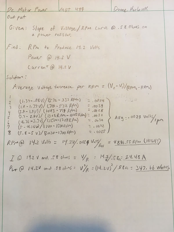
A voltage curve was established with a permanent magnet motor through experimentation to determine motor output at specific rpms.
-
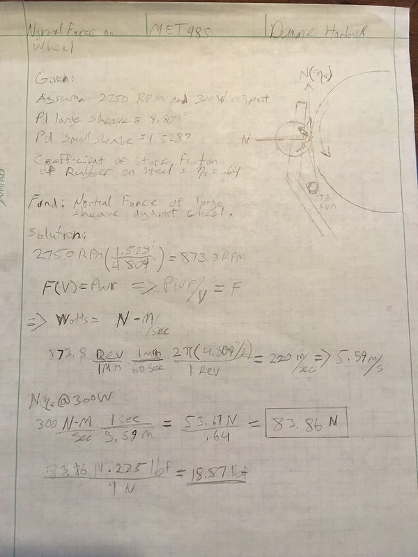
The minimum friction force required to hold the large sheave against the exercise machine wheel was calculated.
-
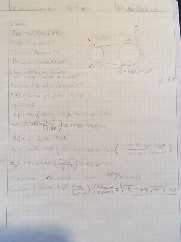
Appropriate pedaling cadence on exercise bikes with 19" flywheels to achieve 2750 rpm output on the motor shaft.
-
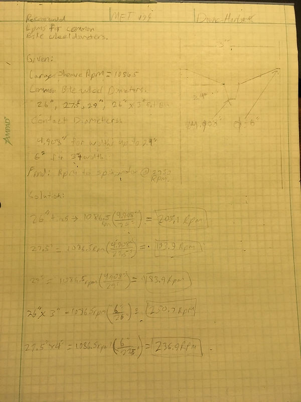
Revolutions per minute on typical bicycle wheel diameters at the contact point of the large sheave were calculated.
-
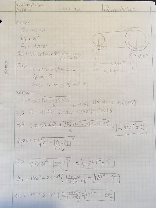
The minimum center distance between the sheaves was calculated for compactness.
-
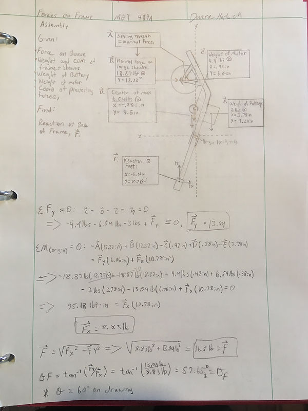
The forces on the frame were calculated in order to determine the spring force required to maintain static equilibrium of the frame.
-
The Shear stress on the spindle was calculated to be used to asses maximum deflection.
-
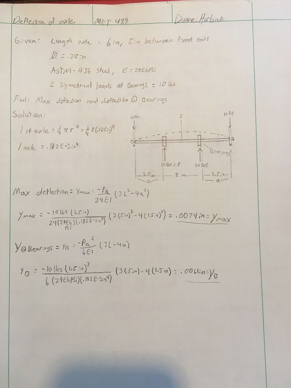
The deflection of the shear stress was calculated to determine if deformation of the spindle at the point of maximum deflection would hinder the large sprocket from freely spinning.
-
A spring design calculation was made to specify an acceptable spring that would maintain static friction at the point of contact between the large sprocket and the exercise machine and accommodate for the additional load due to the weight of the device.
-
An analysis of appropriate roller bearings was made.
-
Weldment calculations were made to determine the maximum force each weld could sustain. These figures assured a robust design.
-
The loads that were placed on the leg connection pins were evaluated to be negligible given their material properties.
-
The center distance between the two sprockets was reevaluated after a design changed.
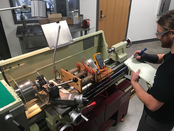
Establishing a voltage curve: A permanent magnet motor was fixed to the tool post of an engine lathe. The input/output shaft was secured within the chuck. The motor was then put in series with a power resistor and two digital multi-meters measuring voltage and current. By changing the loading with the power resistor it was possible to observe the changes in power output with rpms. This analysis was critical in order to obtain an appropriate design for the drive train which included a large sprocket, a synchronous belt and a small sprocket fitted to the drive shaft of a DC motor.
Voltage Curve: (Appendix A12)
The first analysis to be performed was the establishment of voltage per RPM on the motor. This preliminary analysis opened the door to analysis of the input rpms and size of the large interfacing sprocket as well as structural and electrical analysis. This analysis was conducted by locking the shaft of the motor in the jaws of an engine lathe in the Hogue machine shop. The motor was hooked up to a volt meter, amp meter and some power resistors to gain insight into output of the motor at a given rpm and resistance.
Normal Force: (Appendix A4)
The normal force required to maintain static friction at the point of contact between the bicycle wheel or flywheel and the large sprocket was calculated by finding the tangential velocity of the large sprocket at the point of contact. By definition the Watt is an expression of a newton-meter over a second. Using the power output at the specified motor rpm it was possible to calculate the normal radial force on the large sprocket required for a non-slip condition.
Natural Cadence Estimate: (Appendix A1)
A preliminary “lap” was taken on the spinning bike in room 205 of the Hogue Technology building to establish a natural pedaling cadence to produce a desirable input rpm for the dc motor. A natural cadence was estimated to be between 1 and 3 cranks per second. A speed reduction system was designed based on the motor operating at an ideal 2750rmp. Using a 1.9” sprocket on the motor and a 4.8” sprocket against the spinning bike fly wheel yielded a cadence of 1.4 cranks per second.
Cadence Estimation for additional wheel diameters: (Appendix A3)
Additional estimates for required cadence were made for a multitude of standard wheel diameters and thicknesses. The point of contact on the large sprocket was predicted to move outward as the width of the tire increased due to the “v” groove in the sprockets design. This gave a smallest sprocket diameter in the instance of a road bike in an exercise stand and a largest sprocket diameter with a fat bike in an exercise stand. The revolutions required at the bicycle end in order to yield 2750rpm at the motor end were estimated to be between 1.4 and 3.9 revolutions per second.
Center Distance: (Appendix A2)
Once the diameters of the sprockets on the exercise bike generator were established it was possible to estimate the center distance between their axes based on available lengths of belts. A 24” XL Belt was selected.
Frame Statics: (Appendix A5)
In order for the exercise bike generator to function properly it must of course be static with the exclusion of the drive train. The weights of the heaviest components, I.E. The motor and the battery were plotted on an x-y plane along with the center of gravity predicted in the SolidWorks rendering. Using the dimensions established with the SolidWorks modeling it was possible to predict the forces in the x and y directions. The force required to balance the system in the x direction would be a necessary figure to specify the springs that would be used to strap the generator to the given spinning bike or bike in stand configuration. The balancing force in the x direction was predicted to be 16.5lbs
Spindle Deflection: (Appendix A8)
Since the spindle would be loaded in the middle it was desirable to know the maximum deflection of the spindle in order to know if the bowing of the axle would interfere with the spinning of the large sprocket. A beam deflection analysis was used to determine that if two 10lb loads were to be applied to the spindle at the bearings then the maximum deflection of the spindle would be .0074”.
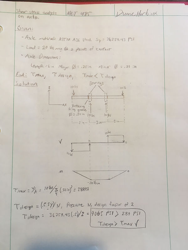
Spindle Shear stress: (Appendix A7)
The design of the generator implemented a .25” diameter A36 Steel spindle. The maximum shear stress on the spindle was calculated to be 289 psi. This load was based on a maximum 20lb load of the springs pulling the large sprocket against the engaged wheel. The figure for maximum shear stress was well below the maximum shear stress for the material even with a design factor of two, which for A36 Steel was estimated to be 9065 psi.
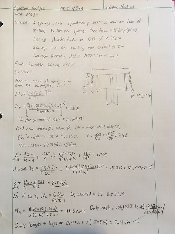
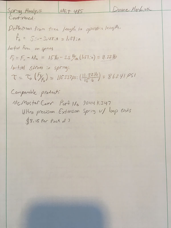
Spring Design and Specification: (Appendix A6)
The loading for the springs was estimated to be between 10-15lbs maximum for each spring. The springs were designed to have a free length of 3 inches and extend to 5 inches in order to provide the necessary loading. During the design process ASTM A227 steel wire was used. The design of the spring specified a .565” diameter spring with a 2.48” body. An extension of 1.51” would provide a load of 11.22lbs. A similar spring that met close enough criteria to the designed spring was selected from McMasterCarr.
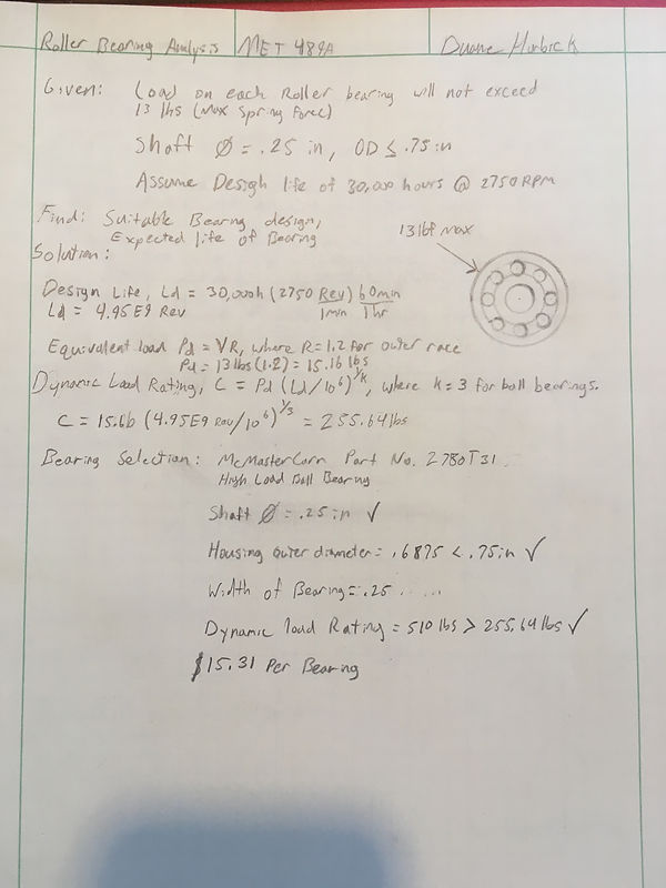
Roller Bearing Analysis: (Appendix A9)
A pair of roller bearings would be required to enable the large sprocket to spin freely on the spindle. A predicted load of 13lbs was specified as well as a design life of 30000 hours of operation which was specified to give the bearings the same relative functioning life as the electric motor. A dynamic load rating of 255.64 lbs was calculated and a suitable bearing was selected from McMasterCarr.
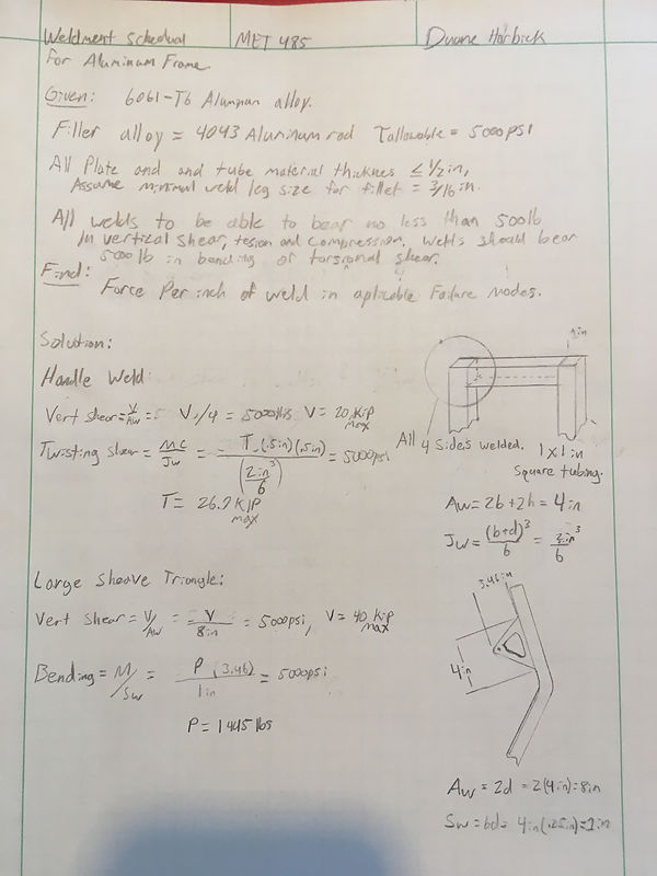
Weldments: (Appendix A11)
For the weldments on the frame of the exercise bike generator it was decided that any of the joints should be able to bear 500lbs in vertical and torsional shear stress and 500lbs in bending stress in order to make a robust frame design. Since the specified alloy for the frame was 6061-T6 aluminum a filler rod of 4043 aluminum was selected. All of the weldments could sustain stresses greater than the specified minimum by and order of 10 with the weld lengths specified.

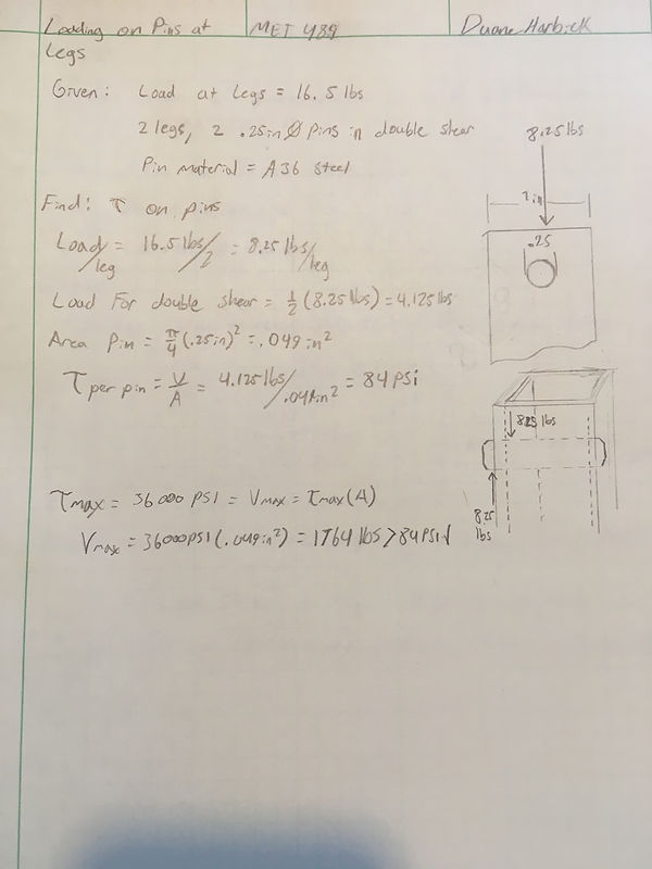
Pin Loading: (Appendix A10)
The pins that connect the telescoping legs to the frame of exercise bike generator would be required to bear the load of the generator, which was estimated to be 16.5 lbs using the SolidWorks assemble and the weighed masses of the motor and the battery. The shear stress on the steel pins was calculated to be 8.25lbs per pin and 84psi per pin which was well below 1764psi which was the estimated maximum shear stress for a .25” steel pin. This enabled the pins to be reduced in diameter if it became necessary for clearance purposes.
Post-facto center distance re-evaluation: (Appendix A13)
The design of the large sprocket on the exercise bike generator evolved several times during the design phase and then one more time when some of the preliminary manufacturing was occurring. The initial design of the generator was intended to be symmetrical, with a “v” belt engaging with a large sheave in the middle of its width. As the design proceeded it was decided that a synchronous belt drive system would be desirable to remove bending stress from the motor shaft.
Finally during the manufacturing phase it was observed that the design of the generator could be made more compact by making the path of the drive train off center from the symmetry of the frame, and bringing the motor in board. This change necessitated a redesign of the spindle and the large sprocket. The teeth on the sprocket which had before been in the middle of the “v” groove of the sprocket were then translated to the outside of the sprocket. Since the diameter of the sprocket was no longer limited by the minimum diameter of the “v” groove it was increased to 5.75 inches, further increasing motor rpms. Since the move was made to a synchronous belt system a smaller 1” sprocket could be used on the motor shaft to further increase the motor rpms.
Since both diameters of the sprockets had changed it was prudent to recalculate the center distance to make sure that the belt that was specified at first was still acceptable. A spread sheet was made to produce the center distances for a range of belt lengths. It was determined that a 24” belt could still be used if the location of the spindle retaining arms were moved upwards, which is what was done. This saved time and money that may have been expended in ordering another size of belt.
