top of page
Design:
The preliminary design constraints for this project were made by sizing some of the equipment that the generator would interface with. Figures 1 & 2 depict the some of the sizing process.

Figure 1: Taking the spinning bike dimensions.
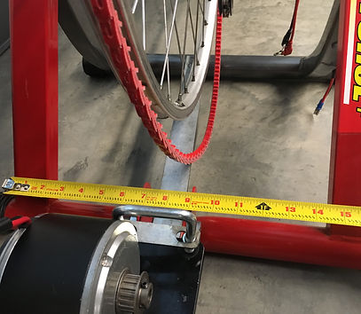
Figure 2: Taking the training stand dimensions.
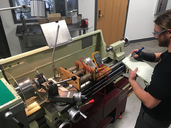
Figure 3: Finding the voltage curve using a power resistor that has been shorted at .5 ohms, a volt meter, and an amp meter.
It was necessary to establish a voltage curve for the motor to determine how fast it would have to spin to put a charge on the 12 volt battery. With this information it was possible to start to design the drive train for the generator. Figure 3 depicts the testing that took place in order find the voltage curve.
Drive train design:
It was decided that the ideal design for the large pulley on the generator should implement a "V" groove that would cope to a wide variety of tire thicknesses to optimize the versatility of the generator. Originally it was intended that the drive train should be a "V" belt drive (Fig 4) with the belt centrally located in the pulley. As the design evolved it turned into a synchronous belt drive with the belt centrally located (Fig 5) and finally, a synchronous belt drive with the belt located on the side of the sprocket (Fig 6, 7, 8, and 9) in order to better center both the large sprocket and the motor within the generator frame.
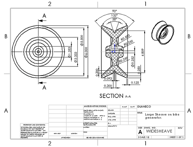
Figure 4: Wide Sheave design.

Figure 5: Wide Sprocket design with centrally located belt drive.

Figure 6: Wide Sprocket design with asymmetrical belt drive.

Figure 7: Wide Sprocket drive geometry.
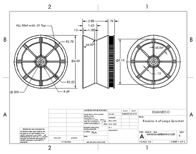
Figure 8: Wide Sprocket Overall dimensions.
Frame Geometry:
The generator frame was designed to cope to different exercise platforms and consisted of a structure on which to mount two adjustable legs, electrical components, and the drive train components. The key components within the frame that allow for adjustment include the telescoping legs and the leg mounting plates depicted in Figures 10 and 11 respectively. The design of the legs allow them to be lengthened from 8 to 16 inches.The adjustable feet on either telescoping leg are threaded and can fine tune the length of the leg as well as accommodate differently aligned tubing. The leg mounting plates allow the legs to pivot 30 degrees inwards and 60 degrees outward in reference to the other vertical members on the frame. The telescoping legs are clamped between the leg attachment plates with a locking cam handle. (Fig 11)

Figure 9: Telescoping leg and adjustable foot.

Figure 10: Leg attachment plates.

Figure 11: Final Assembly

Figure 9: 3 Dimensional rendering of the final design of the wide sprocket.
bottom of page