Construction
Methods and Construction:
Description:
There have been several iterations of this exercise bike generator that have been assembled be previous senior met classes. The goal for the current iteration will be to create an easier to use and more elegant that will still perform the core function of charging a battery. Since many of the necessary components of the bike generator are prefabricated the critical parts that must be made are the frame, spindle, legs, and the sprocket. The frame for the bike generator must provide an adequately rigid foundation for the motor, charge controller, battery, and large sprocket bracket to be mounted to. To accomplish this, traditional fabrication methods that are offered within the various labs in the Hogue Technology building will be used to cut, machine, weld and fasten and aluminum frame, and some adjustable mounting hardware.
-
The exercise bike charger will consist of an aluminum frame that will be constructed from 1 inch 6061-T6 aluminum tubing, ¼ inch 6061 Aluminum plate and 6061 aluminum angle. The main components of the frame will be two bent tubes that will be parallel to one another with plates welded between them. The frame will include two arms that will retain a spindle and 3D printed synchronous belt sprocket at sufficient distance from the rest of the components to spin freely. The plates within the frame will provide a mounting surface for both the motor and the battery.
-
The frame will also include two plates that will provide attachment points for two telescoping legs. The legs will be able to pivot back and forth due to a path milled in the leg mounting plates. The legs are secured in place using a cam handle attached to a threaded stud that goes through the perforations in the leg mounting plates and the legs.
-
The telescoping legs will consist of a 1 inch outer tube and a ¾ inch interior tube. The outer tube will have a 1 inch linear hole pattern drilled in one side to accommodate a button spring that is inserted into the interior tubing. The bottom of the interior tubing will have a welded plug that is drilled and threaded to accommodate a 3/8-16 HSS threaded rod with a “U” shaped steel foot plate welded at its base. The “U” shaped foot plate was designed to but against square and round tubing up to 2 inches in width or diameter.
-
The 3D printed large sprocket will implement a “V” shaped groove that will provide a contact point between the sprocket and a wide variety of wheel diameters. The synchronous drive component of the large sprocket will be located to one side of the sprocket. The sprocket will be mounted to the spindle using two roller bearings with retaining rings to hold it in place. A 24 in XL belt will conduct power from the large sprocket to a 1 inch diameter small sprocket that is attached to the shaft of a 300W 24V DC permanent magnet motor.
-
The motor will be connected in series with a charge controller which will regulated the voltage that is placed on a 12 Volt 5 amp hour sealed lead acid battery. There will be a Volt Amp Watt meter that will display the flow of electricity coming from the motor.
-
The exercise bike generator will be attached to either a spinning bike or a bicycle that is locked within an exercise stand webbing straps with a buckle will be threaded through the free loops of two extension springs attached at either end of the spindle. The buckles on the webbing straps can be used to adjust the length of the straps to provide uniform tension on the springs and fix the generator and frame to the exercise machine.
Tubing:
All of the aluminum tubing was cut to within 1/10 of an inch on the horizontal band saw. Final length dimensions for the bent frame legs, retaining arm gussets, handle, and telescoping tubes were milled to within .005 inches of specified dimensions using an upright mill. The holes in the telescoping tubing and the retaining arms were located laying out the position of the holes with the height dial indicator on the granite slab. A center punch was used to guide the drill tip to the appropriate location.
¼ inch Round Rod and 3/8-16 threaded rod:
¼ inch A36 round rod was used to make the two leg connection pins and the spindle for the large sprocket. The rough lengths were achieved on the vertical metal cutting band saw. The stock was secured using vice grips. The final lengths, chamfers and retaining ring grooves were achieved in an engine lathe with a three jaw chuck. Similar protocol was followed for the threaded rod.


Telescoping Leg Interior Tube
Handle Tube
Retaining Arm Tube
Mounting Plates and gussets:
The .25x1 inch and 1.5x1.5 inch aluminum angle for the motor mounting plates were cut to within 1/10 of an inch on the horizontal band saw and milled in the upright mill to final length. Each were milled with two slots for the 4 M6-12 machine screws required to mount the motor. The slots were specified so the synchronous belt could be tensioned and removed easily. The slots were milled with a ¼ in two flute HSS end mill. Chamfers were milled in the slots using a 45 degree counter sink.
The significantly more involved geometry of the leg mounting plates were designed to allow the telescoping legs to both pivot 45 degrees from side to side and also to allow the legs to be folded out of the way against the frame for storage or interfacing with a wheel that was lower in relation to the bottom of a machine frame. The rough dimensions of the plates were cut on the vertical band saw. The final rectangular dimensions were milled in an upright mill. The corner radii and the curved slots as well as the elliptical weight reduction hole were milled in the Milltronics CNC mill with the use of MasterCam.
The retaining arm gussets were cut to rough dimensions on the vertical band saw. The 45 degree geometry was achieved by laying out a scribed line and clamping the gusset in the vice on the upright mill visually parallel with the scribed line, and milled to specification.

Retaining arm gussets
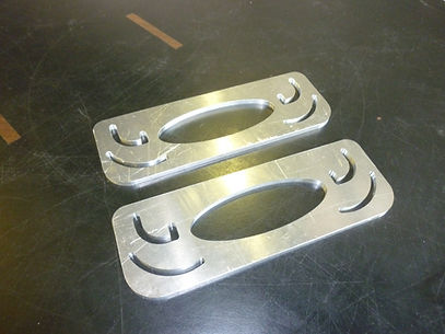
Leg Attachment plates

Motor Mounting angle

Motor mounting plate
Tube Bending:
A square tubing bending die was acquired for the department with assistance from Matt Burvee, for the bending of the two legs of the frame of the generator. The bending die was equal to the task but it required a great deal of physical effort in order to overcome the temper of the 6061-T6 Tubing. When the bends were finally achieved it was difficult to remove the tubing from the die. There was some superficial surface damage the tubing and some twisting did occur. Due to the difficulty of removal from the bending die an angular dimension of 125 degrees was achieve which was in contrast with the specified 120 degrees. This did not affect the function of the generator.

Bent Tubes

Tube Bending Process
Battery Strap:
The rough length of the 1.5 inch wide battery strap was but with the horizontal band saw. The bends were achieved with a 45 degree die mounted in a hydraulic press. Layout of the screw holes was executed with calipers, center punched and drilled in the drill press with a .25 inch HSS drill bit and counter sunk.
Aluminum welding:
To achieve the appropriate spacing and geometry for the welding of the frame Doug fir spacing blocks were cut to locate both of the mounting plates, the retaining arms, retaining arm gussets, and leg mounting plates. The spacer for the leg mounting plates included two holes located precisely with an upright mill to locate the .25 inch leg mounting pins within the mounting plates in order to maintain parallel orientation of the leg mounting plates. All weld locations were initially tack welded so that the fit of the motor and the large sprocket could be checked before the final welds were made. It became necessary to use significant clamping force to pinch the bent tubes into an acceptable position because of some twisting that occurred in the bending process. The welding of the plugs in the interior telescoping legs required little setup or special preparation. The plugs were then drilled and taped with 3/8”-16 threads.

The spacers used for the welding setup.
Foot Plates:
The foot plates were rough cut in the horizontal band saw. Their centroids were located using calipers and were then drilled using a center drill for boring after the bending process. The foot plates were initially bent using the hydraulic press. The final bending was achieved via a forging process wherein an oxy-acetylene torch set up with a rosebud tip was used to heat the leg plates to 1800-1900 degrees F. Vice grips and pliers were then used to wrap the leg plates around a 1.5 inch diameter round piece of aluminum to achieve an appropriate radius. The leg plates were allowed to cool at room temperature after forging. They were then drilled and taped with 3/8”-16 thread. The threaded rod was then screwed flush with the inside radius of the leg plates and welded in place.

Adjustable Foot Plates with threaded rod.
3D Printed Sprocket:
Several different options were explored for the printing of the large sprocket. It was estimated that 3D printing using the ABS printers in Hogue would cost approximately $170. The new 3D printer in the Hogue Technology building made use of significantly cheaper PLA filament could theoretically print two of the large sprockets for less than $20, but it’s some of its mechanical components failed during printing and it was unable to print the part. The large sprocket ended up being printed in Black Hall with PLA filament for a fee of $23.49. The white PLA filament that was chosen for the part ran out nearing the end of the print and was replaced with a magenta PLA filament to give it a very striking aesthetic detail. Some modifications to the 3D printed sprocket were required to achieve function. The bearing seat, and the bore for the spindle had to be widened to achieve their function. Once the appropriate bores were achieved the large sprocket was mounted on the spindle and the spindle placed in a ¼ in hole drilled in a large wooden block so that it could stand up and be spun freely. All parts of the large sprocket except for the “v” groove surface were covered with masking tape. The sprocket was then spun and sprayed with rubber tool dip which was able to penetrate into the 3D printed matrix with good resulting adhesion. The purpose of the tool dip application was to decrease the coefficient of friction between the large sprocket and the mating wheel.
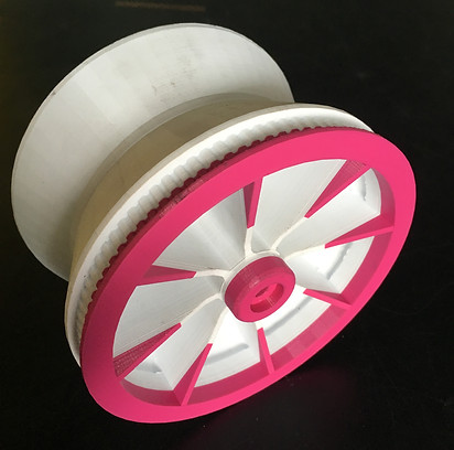
3D Printed Sprocket

3D Printed Sprocket with tool dip coating, bearings, spindle and bushings.
Nylon Bushings:
Two nylon bushings were required to mount the springs to the outside of the spindle. Their outer diameter, inner diameter, and groove for the spring loop were all turned on the lathe. The bushing was then parted from the solid nylon round and deburred.
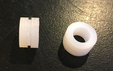
Nylon Bushings
Final Assembly:
To assemble the telescoping legs some modification was required to allow the button spring to articulate freely from hole to hole. A Dremmel tool was used to relieve the inside of the exterior tube at a sufficient angle to allow the button spring to slide easily from position to position. Due to the twisting of the bent tubes, parallelism with the leg mounting plates was out of specification. This disallowed the telescoping legs to articulate through the paths that were milled in the leg mounting plates. This problem was addressed by widening the radiused slots with a die grinder until functionality was achieved. The holes in the exterior telescoping tubing which accommodated the locking cam handles were drilled oversize to allow the threaded studs to slide freely through their slot in the mounting plate. Four 6-32 holes were drilled and tapped into the back of the tubing frame to mount the charge controller. The motor, small sprocket, XL belt, as well as the sprocket and spindle assembly required no special treatment in assembly. The loops for the extension springs did however have to be bent open and then closed again over the nylon bushings.

Final assembly and weight.
Electrical Design Modifications:
After initial testing it was determined that there were two flaws in the electrical design of the generator. The first being that the Volt, Amp, Watt meter would only measure electrical properties if current was flowing through it in a specific path. It would not measure anything if the power was going through the meter backwards. This became an issue because in order to adapt to the different exercise platforms the generator also had to be able to generate power while interfacing with wheels spinning in either direction. To solve this issue a bridge rectifier was constructed using four 10Amp10 diodes. This ensured that current would flow the right direction no matter what. The second issue was determined to be the solar charge controller that was acquired for the generator. The solar charge controller had some somewhat sophisticated power point tracking programming that was suited to solar panels and not the erratic power generated by a human cadence. It was necessary to retrofit the generator with an older solar charge controller that only prevented the 12 volt battery from over charging.

The bridge rectifier design and the "dead bug" style bridge rectifier.

The older charge controller that supplanted the newer charge controller.


All Videos
Assorted Videos of Some of the construction processes.
Parts List:
Device Frame
-
1" by 24" 6063 Aluminum Tubing (Alcobra)
-
1/4" by 12" by 12" 6061 Aluminum Plate (Alcobra)
-
1-1lb Gas Welding Rod (McMasterCarr)
-
1-Pack(3) Extension springs (McMasterCarr)
Telescoping leg
-
1" by 12" Telescoping Aluminum Tubing (Alcobra)
-
3/4" by 12" Telescoping Aluminum Tubing (Alcobra)
-
1-Pack(5) Stainless Button Springs (McMasterCarr)
-
2-High Strength Steel Threaded Rod (McMasterCarr)
-
3/16"x1"x12" 1018 CR Steel Flatbar (Alcobra)
-
2-1/4"x1.75" Chrom Moly Rod (Alcobra)
-
4-1/4” OD Black Phosphate Steel External Retaining Ring (97633a130)
Electronics
-
1 Uxcell Intelligent 25A Charge Controller
-
1-MY1016 24V 300Watt DC Motor
-
1 Windy Nation Watt Volt Amp Meter
-
1-12V Lead acid Battery
-
Wiring
-
Fasteners
Drive Train
-
1 kg Hatch box ABS 2d Printer Filament
-
1-Lightweight Timing Belt pulley (McMasterCarr)
-
1-XL Series Timing Belt (McMasterCarr)
-
1-Pack(100) External Retaining Ring (McMasterCarr)
-
1-1/4"x7.5" Chrom Moly Rod (Alcobra)
-
4-1/4” OD Black Phosphate Steel External Retaining Ring (97633a130)
-
2-Ball Bearing (McMasterCarr)
-
Plasty Dip
Cut List:
1” aluminum tubing
-
2: 20”
-
2: 3.5”
-
1: 7”
¼” aluminum plate
-
1: 4”x5”
-
2: 3.25”x9.5”
-
1: 1.5”x4”
Telescoping aluminum tubing
-
2: 1”x10”
-
2: .75”x8”
3/8”-16 Threaded Rod
-
2: 2”
3/16 mild steel flat bar
-
2: 5.5”
¼” A36 Steel rod
-
1: 7.5”
-
2: 1.75”

All of the manufactured and modified parts.